A case of the bad capacitor
When doing your dumpster diving tours/raids, it's not unusual to find monitors lying around. Fortunately enough those huge old CRTs are mostly long gone as people want to use their desktop space to store other meaningless crap such as papers and forgotten bits of food. And coffee mugs. So you grab the monitor and balance it on your bike all the way home - proud of today's rescue from destruction.
But when you get home and turn it on, either it doesn't light up at all or perhaps it powers on up but won't display anything. "Garbage!" you think, disregarding that you got it from a dumpster. However, this may very well happen to you while at home - suddenly the display doesn't work! And buying a new one seems to be cheaper than handing it in for repairs. But alas, read this tutorial and you may get inspired to fix the problem yourself!
Step 0 - Introducing your common foe
There are some ordinary problems that occur for just about any home-electronic device in due time. It's a case of the Bad Capacitor. The capacitor is an electronic component which temporarily stores an electrical current - kind of like a battery but it can discharge much, much faster. The capacitor is a standard component, and it's usually the larger "electrolytic" capacitors which are troublesome. Fortunately, they're very cheap and easy to replace!
Step 1 - identify the problem
I've skipped the steps of opening the monitor because it's unique to basically every case out there. Unscrew, unsnap, tear and cry. Those are my tips. Just make sure you don't have a screw loose in the end (or missing).
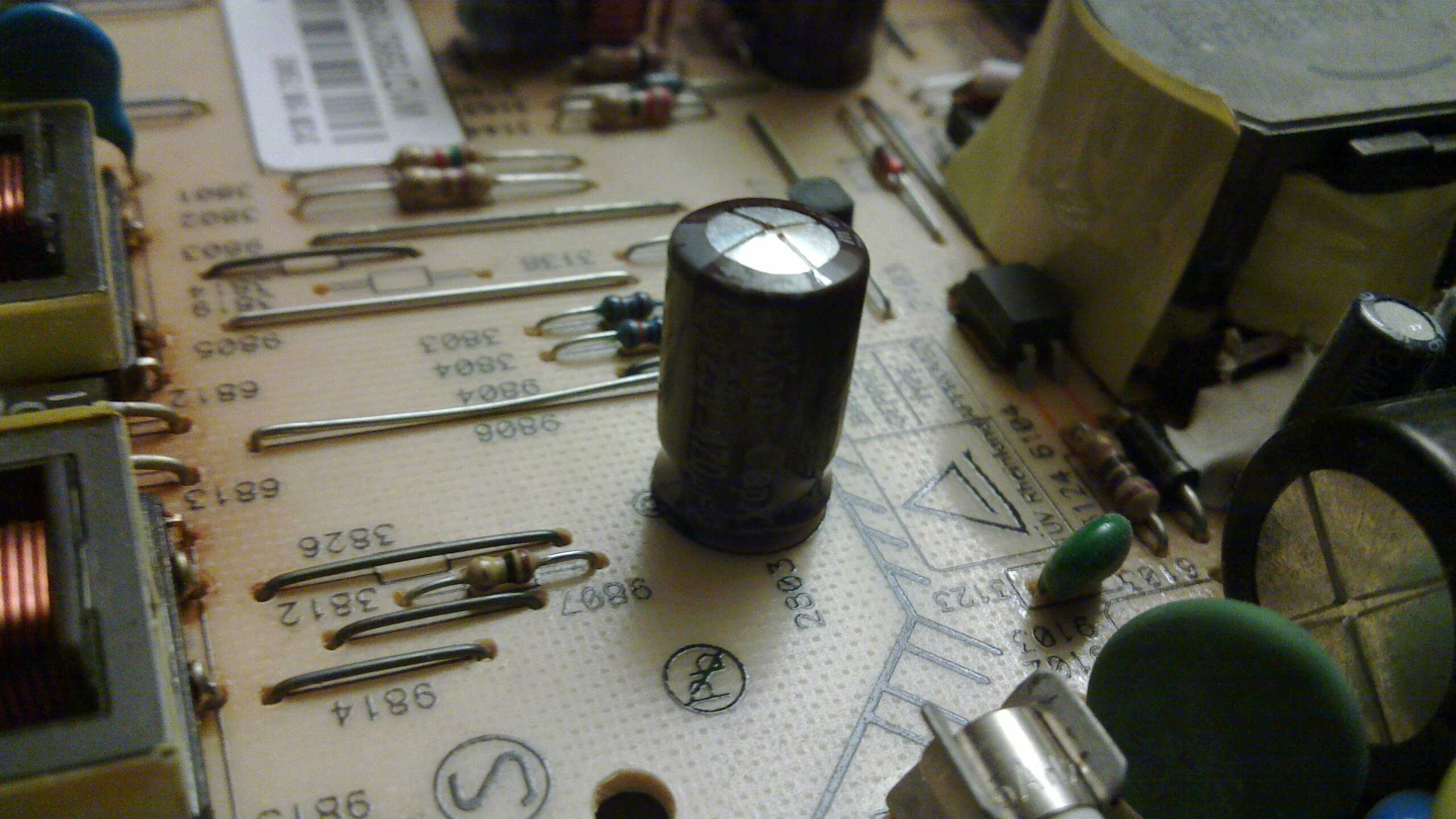
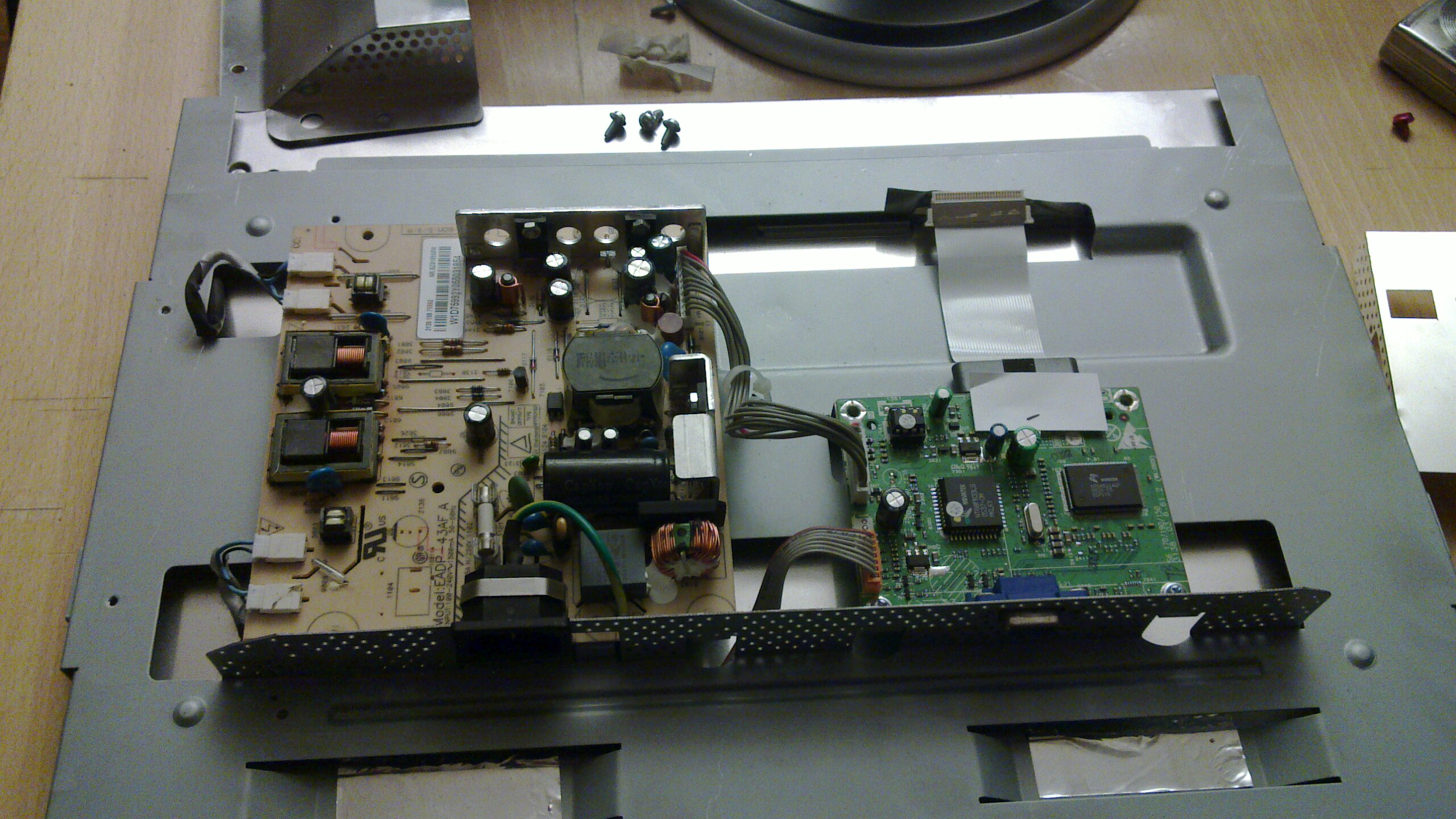
Having removed the front case and taken out the actual screen, I looked at the two PCBs attached, one of which had the monitor signal going in and the other one obviously being the PSU. As you can see above, and compare with the other similar components on the pictures, these are obvious culprits in the misbehaviour of my monitor. Nothing bulging that much can be healthy!
Now, of course there might be other problems causing your display to malfunction. It might just be a fuse that's blown or badly soldered connection. These aren't quite as obvious or in-your-face dilemmas, as the components are smaller, but usually you can identify this by looking at the fuse or locating tiny burned spots on the PCB. If that's the case, just replace the fuse or resolder the contact area!
Step 2 - Fixing the problem
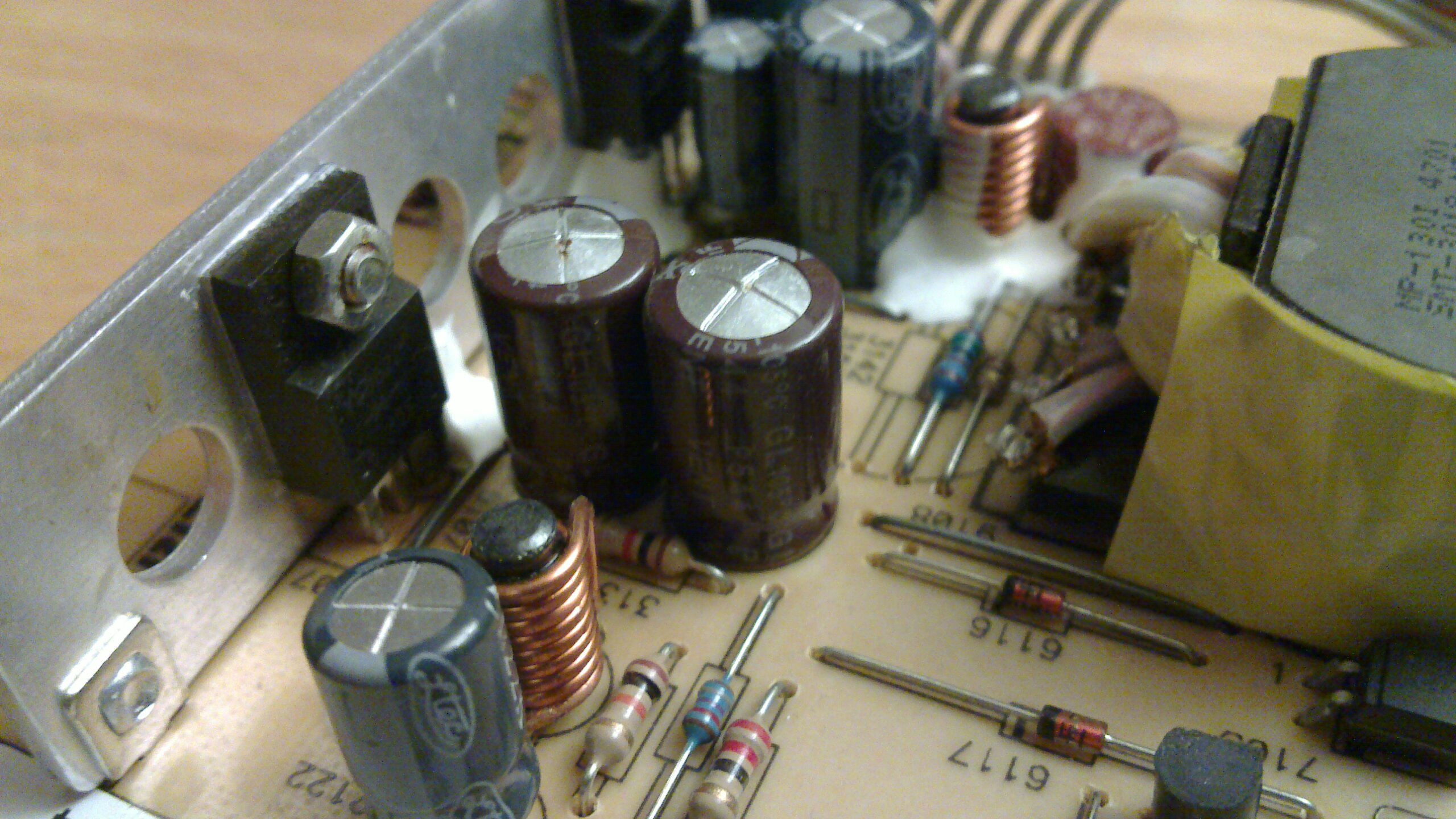
If you, as I did, found components that need to be replaced it's sort of important to replace it with a nearly identical component. In my case I found three larger capacitors rated 470µF and 25V. The voltage is a maximum specification of the circuitry, so go ahead and use anything above 25V, such as 50V which is also common and cheap. You could probably go lower as well, as practical use of components is not really an exact science. As long as you plug your positive and negative sides correctly - especially for electrolytic capacitors - merely replacing components this was won't make your scrapped monitor anymore unusable!
[caption id="attachment_134" align="aligncenter" width="300" caption="Bottom-view when capacitors have been removed and the solder has been sucked so I can reuse the holes."]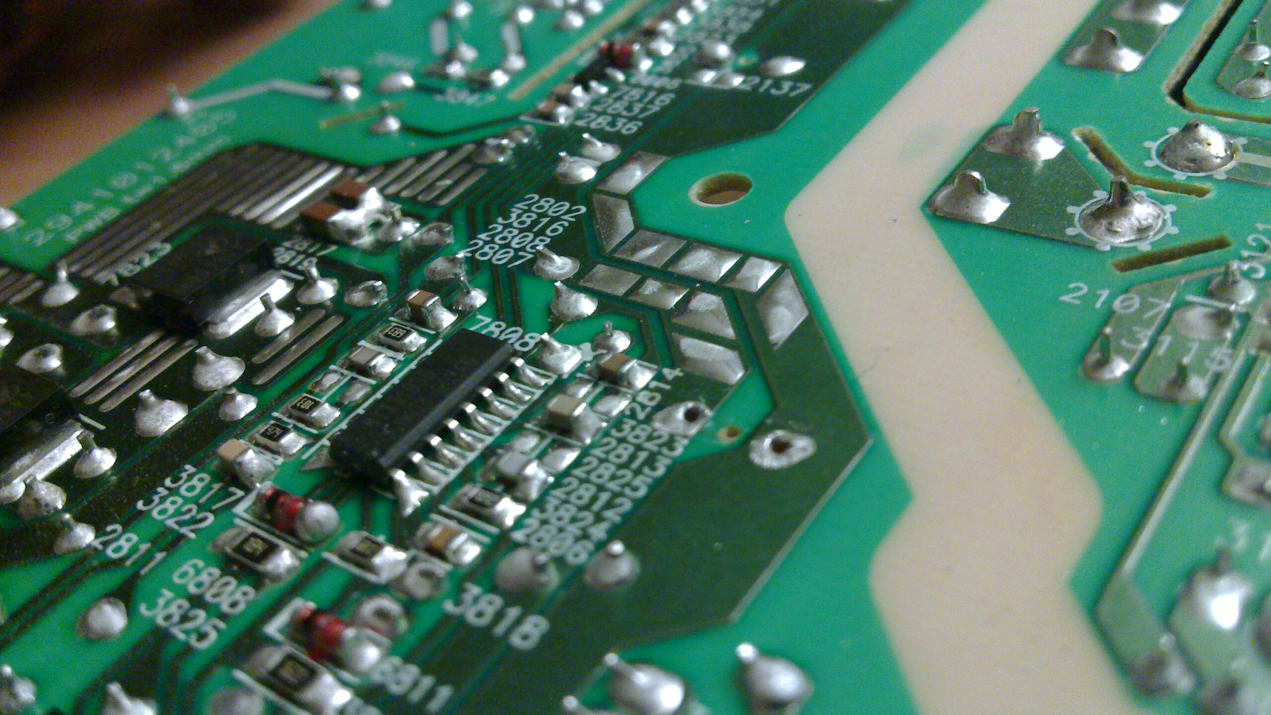 [/caption]
The rating 470µF is the capacitance, i.e. how much current it can store. The usage is generally an approximation where it's possible to use a relatively wide range of components with various specifications. As mentioned it's not an exact science, so don't be afraid to experiment! A great way to get hold of replacement components is to strip other electronics of their counterparts - if nothing else, it might at least teach you how to solder off components. Instead of doing what I did, which was a bit more violent (and struggling when filming it with one hand):
[youtube EgBG_2wRqyk]
What's interesting with this specific board was that it used two capacitors in parallell at one of the spots. These two 470µF capacitors in parallell are equivalent to one 940µF, which means that if you happen to have a 1000µF capacitor lying around it would do just fine to replace the other two. However with possibly multi-layered PCBs and hidden lanes, I'd be careful to guess around too much with this. But in theory it's doable! Be my guest and try this at home.
[caption id="attachment_135" align="aligncenter" width="300" caption="The three replaced and the three replacees."]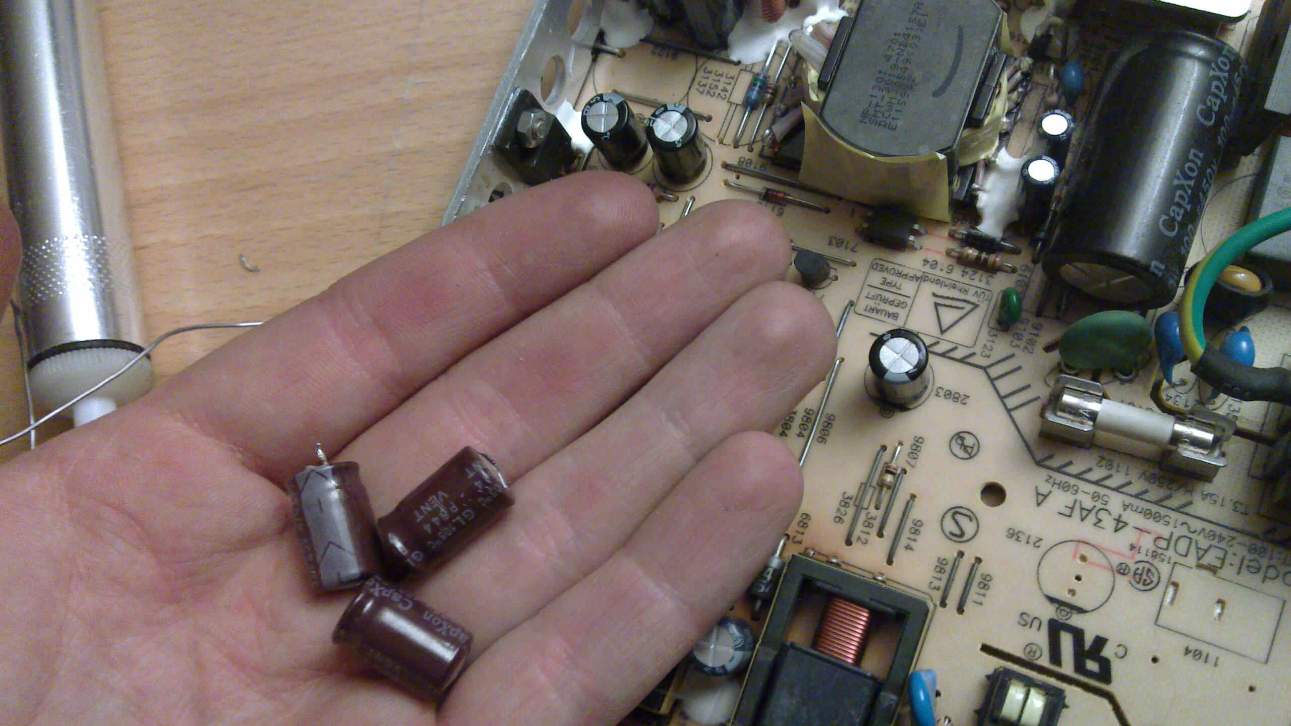 [/caption]
Step 3 - It's as simple as that
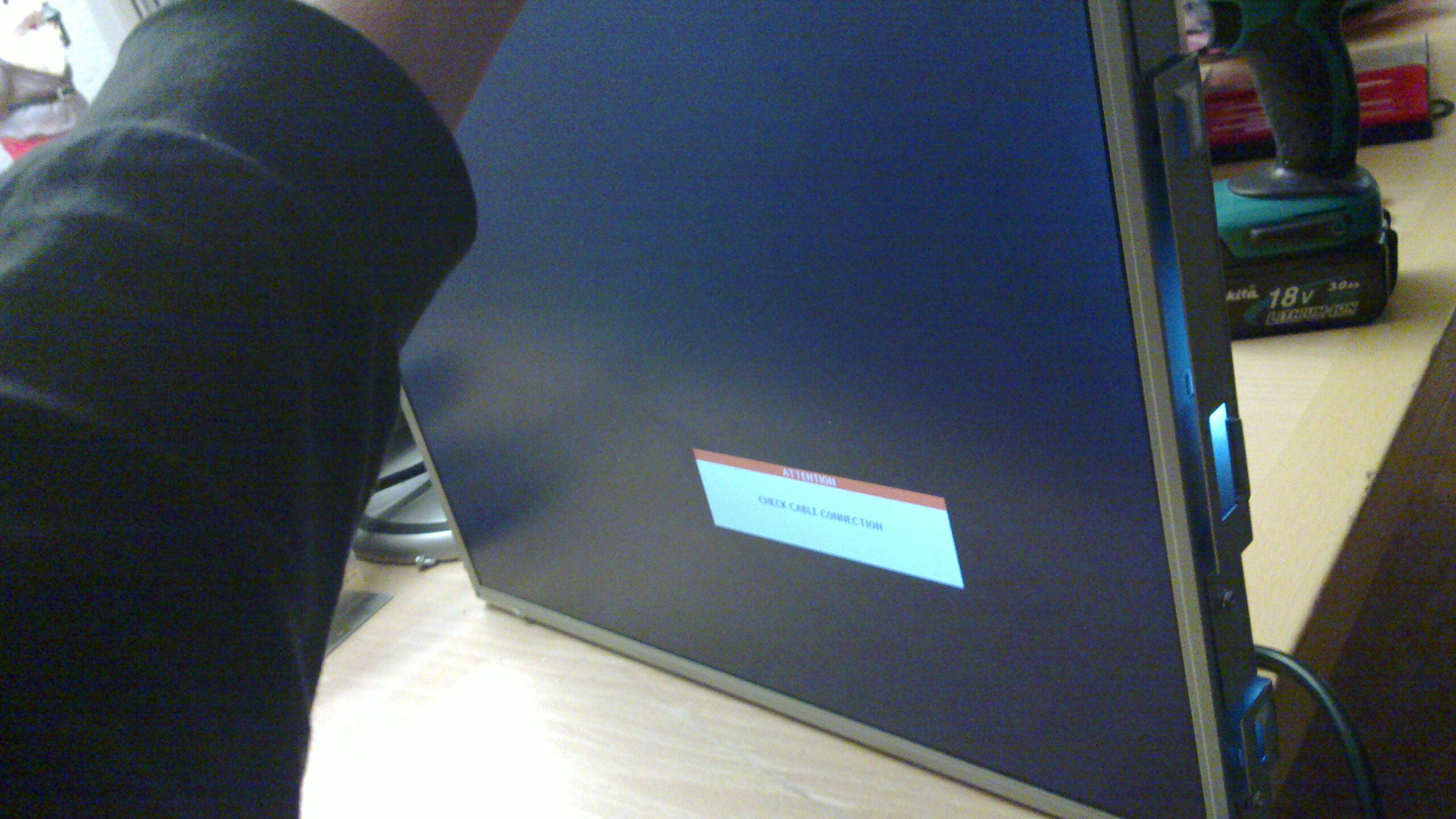
There we go. Soldered and done. Now it just remains to put back the screws, connect the cables and see whether it works or not. In my case I had problems with a very bad analog signal to the LCD matrix, which was the result of being too violent when first opening the case. I had managed to disconnect the shielding, and probably reconnected the cable itself badly, so all kinds of disturbances showed up and gave me a working monitor with a very bad image. But as long as you remember what you fiddle with, most problems are traceable and relatively easy to fix!
Thanks to: Mrw00t who actually dumpstered these monitors and Philips who made a monitor that's actually quite easy to open!